xv6启动过程(1)
加电启动:BIOS
现代的x86系列处理器为了保持前向兼容性,在加电启动时会工作在与8086系列处理器相同的实地址模式下。基于Intel 8086处理器的早期PC拥有1MB(20位)的地址空间,其分布如下[2]:
使用16位寄存器在20位地址空间中寻址需要用到两个寄存器,以CS:IP的形式表示,目标地址为CS << 4 + IP. 加电时,CS寄存器被置为0xF000,IP寄存器被置为0xFFF0(这里与8086的原始spec并非完全一致,见manual 2-29页),因此位于0xFFFF0处的BIOS代码成为被执行的第一条指令。这个位置靠近地址空间上界,所以一般是一条JMP语句,跳回BIOS区中之前的某个位置执行BIOS逻辑。BIOS与具体操作系统无关,一般与主板关联,本例中由QEMU提供,完成硬件的初始化工作。
Boot Loader接管
BIOS找到引导设备后(如硬盘),从其(这里为xv6.img)首部加载512字节的第一个扇区到物理地址0x7c00处并跳转到这里,进入bootasm.S的逻辑:
1 | .code16 # Assemble for 16-bit mode |
BIOS的工作中可能需要设置自己的中断处理程序并开中断,在加载xv6时不需要用到,所以使用cli关闭中断。BIOS完成工作后,3个段寄存器中的值不确定,所以将其清零。
启动A20地址线
背景[6][7]:之前提到8086的寻址方式是CS << 4 + IP,由于进位的存在,可能会加出一个21位的地址。8086会把多出来的A20地址线置零,而部分早期程序依赖了这个特性。因此为了保证前向兼容,后续型号的CPU默认禁用了A20地址线,需要手动开启。开启这一地址线的方法依赖了键盘控制器中的一个空闲位,虽然它们在功能上毫无联系。
1 | # Physical address line A20 is tied to zero so that the first PCs |
端口0x60和0x64与键盘控制器有关,通过向端口0x60写入数据启用A20地址线;每次写入前需要在0x64处监听键盘控制器是否忙碌,直到设备空闲方可写入。
进入protected mode
准备GDT
背景[8][9]:
不同于real mode下的寻址方式,保护模式下段寄存器不再直接存放所谓“段基址”,而是存放全局描述符表(Global Descriptor Table)中某条目的索引。该条目应包含某段的起始地址,此即为段基址,加上偏移量以得到物理地址。
x86下某GDT条目的结构如图:
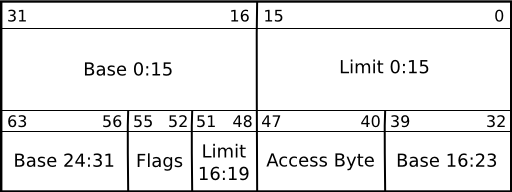
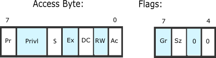
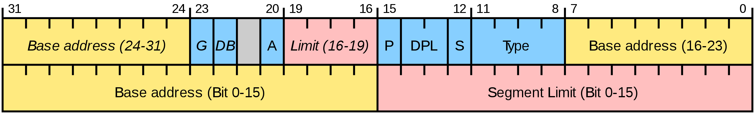
黄色部分组成了段基址,红色部分标记了段的长度,蓝色为状态标记位,意义可参见[10]。
xv6中的GDT如下:
1 | # bootstrap.S |
1 | // asm.h |
可以看出,SEG_ASM宏将P位(该条目有效),S位(非系统段),G位(limit单位为页,即4KB),DB位(32位模式而非16位)均置位,将DPL(Descriptor
Privilege Level,特权级)设为0.
xv6不关注权限位这一安全机制,它们都被置0.
注意该宏对lim的操作抛弃了低12位而取高20位,这是因为G(ranularity)位已经将limit单位设为4KB,不需要再关心低12位的值。
xv6设置了空段(某些模拟器需要)[9]和code, data段,这两个段基址均为0,limit均为4GB,这样分段其实只是走了形式。Linux也采用了这种“平坦内存模型”,依赖分页机制管理内存[8]。
设置GDT
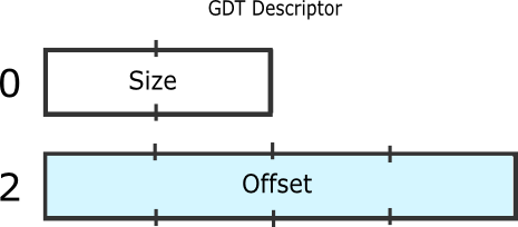
x86拥有一个GDTR寄存器存储关于GDT的信息,其前2个字节为GDT的Size,后4个字节为GDT的起始地址。lgdt指令将指定位置的6字节数据读入GDTR寄存器。随后通过将CR0寄存器的LSB置位,进入protected
mode.对寻址方式的变更以及从16位到32位的变换不是立即发生的,而是在下一次重设段寄存器的时候进行[6],因此movl %eax, %cr0的执行仍在real
mode下进行,没有问题。
1 | # Switch from real to protected mode. Use a bootstrap GDT that makes |
1 | # Bootstrap GDT |
这里的size被设为了sizeof(gdt)-1,可参考[11]。大意是GDT最多可为65536个字节(因为段寄存器有32位,可以索引这么多字节),但是32位寄存器存不下65536这个数,所以就将大小减1后存放。这也是GDT为什么要有一个空段的部分原因(大小不能为0)。
重设CS:IP
通过一个ljmp指令重新设置段寄存器和指令寄存器,以支持保护模式下的寻址模式。SEG_KCODE是代码段的索引值1,左移3位是因为每个GDT条目大小为8字节,CS存放某条目的起始地址。
1 | //PAGEBREAK! |
准备进入bootmain
1 | .code32 # Tell assembler to generate 32-bit code now. |
此处开始生成32位汇编代码。首先设置各段寄存器的值,之后将%esp设为bootstrap汇编代码的起始位置(0x7c00),栈会向下生长且不会与该段代码碰撞。最后调用bootmain,该函数不应返回,但有处理这一异常情况的代码(死循环)。
bootmain
bootmain.c将kernel从磁盘读入内存。
代码逻辑
1 | void |
首先从offset=0处读取一页(4KB)数据,判断其是否为elf文件。之后遍历program
header,将各段(以off为首的filesz长度的段)读入由paddr指定的物理内存地址处。如果一个段的memsz比filesz更大(比如有.bss节),还需要用0填充多出的部分。最后跳转到elf
header中指定的entry入口点:这是通过将一个函数指针指向entry并调用实现的,汇编层面上相当于call *addr,addr为entry所在的物理地址。
ELF header 分析
使用readelf查看kernel的segment和section如下:
1 | Section Headers: |
.text节开始于0x1000,长度为0x70da;.rodata节需要对齐到32字节,故起始位置从0x80da对齐到0x80e0;.data节需要对齐到4096字节,故起始位置从0x8aab对齐到0x9000;.bss节需要对齐到32字节,故在内存中的起始位置需要从0xb516对齐到0xb520。因为.bss节在elf文件中不需要占据空间,它的起始位置应与随后的,应对齐到1字节的.debug_line节一致,故仍为0xb516。
00段为代码段,包括.text和.rodata节,起始位置为0x1000(与.text节一致)。它的filesz和memsz一致,均为0x7aab,与.data节终结于0x8aab的结论一致。
01段为数据段,包括.data和.bss节,起始位置为0x8000(与.data节一致)。它的filesz为0x2516,与.data节的size一致;它的memsz为0xd4a8,等于.data和.bss节的size之和(0x2516+0xaf88),再加上.bss为了对齐而后退的0xa个字节。
TIPS:
可以在qemu中使用
Ctrl+a c进入command界面,再用info registers查看包括GDTR在内的控制寄存器。gdb的反汇编对
lgdt的解析(0F 01 16 78 7C)不太正确,0F 01是opcode,16是ModR/M,78 7C是gdtdesc首地址。为了使用vscode+gdb调试xv6,需要在启动gdb前准备好qemu并监听端口。虽然
launch.json中有preLaunchTask字段,但是启动qemu的task需要监听端口而不会结束,导致调试任务等待preLaunchTask完成而无法继续。为了解决这个问题,可以依赖vscode自带的problemMatcher的tricky用法,参见How to make vscode not wait for finishing a preLaunchTask? 另外要在.gdbinit里面删掉target remote的部分,因为连接到qemu的动作已经在launch.json里进行了,避免重复。在
bootmain.c中,readseg会委托工作给readsect以扇区为单位读取硬盘,如果offset没有对齐扇区边界,会覆盖pa之前的部分内容。readsect通过映射到端口1F0-1F7的硬盘控制器与硬盘交互,其中1F0为数据寄存器,1F7为状态寄存器(读出)/命令寄存器(写入)。从
Makefile文件中构建xv6.img的过程可以看出,引导块占据了0号扇区(512字节),1号扇区开始存放kernel。[13]指出mmu启动前的符号因为直接使用了物理地址,而无法被gdb定位并打断点,这个现象不仅存在于linux kernel,也存在于xv6中。文中提出的修改
.text符号表的方式使gdb同时在物理/虚拟两个地址处设置断点,有效解决了这一问题。1
2
3
4
5
6
7
8
9
10
11(gdb) b entry
Breakpoint 1 at 0x8010000c: file entry.S, line 47.
(gdb) b *0x10000c
Breakpoint 2 at 0x10000c
(gdb) c
Continuing.
The target architecture is assumed to be i386
=> 0x10000c: mov %cr4,%eax
Thread 1 hit Breakpoint 2, 0x0010000c in ?? ()
(gdb)对
entry打的断点落在了虚拟地址空间中,而这条语句实际是在物理地址空间0x10000c处被执行的,后一个断点才会命中。1
2
3
4
5
6
7
8
9
10
11
12
13
14
15
16
17
18
19
20
21
22
23
24(gdb) add-symbol-file kernel -s .text 0x100000
add symbol table from file "kernel" at
.text_addr = 0x100000
(y or n) y
Reading symbols from kernel...
(gdb) b entry
Breakpoint 1 at 0x10000c: entry. (2 locations)
(gdb) c
Continuing.
The target architecture is assumed to be i386
=> 0x10000c <entry>: mov %cr4,%eax
Thread 1 hit Breakpoint 1, entry () at entry.S:47
47 movl %cr4, %eax
(gdb) b main
Breakpoint 1 at 0x103040: main. (2 locations)
(gdb) c
Continuing.
The target architecture is assumed to be i386
=> 0x80103040 <main>: endbr32
Thread 1 hit Breakpoint 1, main () at main.c:19
19 {
(gdb)可以看到
b entryb main同时设置了两个断点,无论代码实际执行在虚拟地址空间(高)或物理地址空间(低)都能命中。
- [原创]BIOS 入门之一: 8086 模式 (ufoit.com)
- Homework: bootstrap and x86 assembly (iitd.ac.in)
- xv6 bootstrap部分源代码分析 | 南国倾城 (wjqwsp.github.io)
- Booting an Operating System (rutgers.edu)
- 9800722-03_The_8086_Family_Users_Manual_Oct79.pdf (bitsavers.org)
- boot.pdf (columbia.edu)
- A20 Line - OSDev Wiki
- 【学习xv6】从实模式到保护模式
- GDT Tutorial
- Global Descriptor Table
- Why in xv6 there's sizeof(gdt)-1 in gdtdesc
- 【学习Xv6】加载并运行内核
- linux内存子系统 - qemu调试linux 内核启动